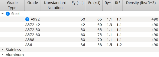
WT Grades
These settings are stored for your currently selected Connection design method.
- General Overview
- Tips and Tricks
- Related Tools
To add a new Grade Type or Grade, right-click inside the table and select Add Grade Type or Add Grade.
Available Settings by Design Method
| Screen | Columns | When Shown |
| ASD/LRFD/CISC | Grade Type, Grade, Nonstandard Notation, Fy, Fu, Ry, Rt, Density | shown when an ASD, LRFD, or CISC Connection design method is selected. |
| AS4100 | Grade Type, Grade, Nonstandard Notation, Fy, Fu, Minimum Thickness, Maximum Thickness, Density | shown when AS 4100 is the Connection design method. |
| Eurocode | Grade Type, Grade, Nonstandard Notation, Fy, Fu, Minimum Thickness, Maximum Thickness, Correlation Factor, Density | shown when EUROCODE3 or EUROCODE3 UK is the Connection design method. |
Settings
Grade Type: Any text string (up to 29 characters) to denote the name of the grade type (e.g., Steel, Stainless, Aluminum).
Grade: Any text string (up to 29 characters) to denote the name of the grade (e.g., A36, A401, Peter, Joe, whatever name you want). Grades entered here are selectable ![]() )
)
Nonstandard Notation: Any text string (up to 29 characters) to denote that a particular grade is not the standard grade.
| For member main material: This Nonstandard Notation string may be made to appear as a part of the section size of a member whose main material is tee material. In a Modeling erection view, the notation appears when Section sizes are shown and the Denote non-standard material setup option is turned on. To get the annotation on an erection view drawing, you need to check the box for Denote non-standard material when you auto detail the erection view. Example 1: Enter * as the Nonstandard Notation for all lines but the first line if you wanted section sizes for tee member main materials with nonstandard grades to be marked with a *. Example 2: Enter (A588) for A588 steel if you want (A588) to be displayed in the model next to the member's section size when A588 is selected |
| For submaterials: A callout is generated next to that material's submaterial piecemark callout on the member detail when Home > Project Settings > Fabricator > Piecemarking > Member and Material Piecemarking > Submaterial > |
Minimum Thickness & Maximum Thickness (AS4100 and Eurocode): These columns let you assign Fy (yield strength) and Fu (ultimate strength) values to a grade based on the thickness of the tee material.
Fy: The yield strength of the grade. If you are using imperial dimensioning, yield strength is measured in kips/sq. inch (ksi). If you are using metric dimensioning, yield strength is measured in megapascals (MPa). The value you enter for Fy is used to design connections.
Fu: The ultimate strength of the grade. If you are using imperial dimensioning, ultimate strength is measured in kips/sq. inch (ksi). If you are using metric dimensioning, ultimate strength is in megapascals (MPa). The value you enter for Fu is used to design connections.
Ry (ASD/LRFD): The ratio (no units) of expected yield stress to the specified minimum yield stress, Fy. See section I-6 of the AISC Seismic Design Manual. This overstrength factor is used during connection design for calculations related to member strength when the user has specified a Seismic brace (vertical brace). The default values used for Ry come from Table I -6 -1 of the AISC Seismic Design Manual. Ry is used only when the governing load (Tension load or Compression load) is ![]() Auto
Auto
Rt (ASD/LRFD): The ratio (no units) of the expected tensile strength to the specified minimum tensile strength, Fu, as related to overstrength in material yield stress Ry. See section I-6 of the AISC Seismic Design Manual. This overstrength factor is used during connection design when the user has specified a Seismic brace. The default values used for Rt come from Table I -6 -1 of the AISC Seismic Design Manual. Rt is used only when the governing load (Tension load or Compression load) is ![]() Auto
Auto
Density: The density value of the grade. If you are using imperial dimensioning, density is measured in lb/ft3. If you are using metric dimensioning, density is measured in kg/m3. The value you enter for density is used to calculate material weight.
Correlation Factor (Eurocode): The appropriate correlation factor (ß w ) taken from Table 4.1 in BS EN 1993-1-8: 2005, Eurocode 3: Design of steel structures. The factor is used in calculations for fillet welds.


|
|
OK (or the Enter key) closes this screen and applies the settings.
Cancel (or the Esc key) closes this screen without saving any changes.
Reset undoes all changes made to this screen since you first opened it. The screen remains open.
- Cut ( Ctrl + x ), copy ( Ctrl + c ) and paste ( Ctrl + v ) are available to help you more quickly edit grades.
- To delete a grade, left-click to select the grade, then right-click and select Erase grade.
- To move a line up or down in priority: Left-click to select the line and hold down the left-mouse button, then drag the line up or down.
- Before beginning to input a Job, you may want to make the Tee sections connection material grade match the grade entered to line 1 on this table.
- Red or yellow exclamation point icons
 or
or 
- Change Grade
- Add Member
- Edit Member
- Add Material
- Edit Material
- Tee sections
- Grade (Status Display)
- Material grade (Status Display)

